Computer Science AS
Introduction Information Representation Communications Communications 2 Hardware Logic Circuits Processor Fundamentals Assembly Language Monitor & Control System Software Security, Privacy & Data Integrity Ethics DatabasesAS Practical
Algorithm Data Structures and more Software developmentComputer Science A2
Data Representation File Organisation Advance Logic GatesInternet Virtual Machines System Software Encryption & Security Artificial IntelligenceA2 Practicals
Binary Search Linear Search Bubble Sort Insertion Sort Combined Algorithm Stacks Queues Linked List Binary TreeMore
Reference Pastpaper Questions
Logic Circuit
Types of Logic Circuits
There are two types of logic circuits depending on whether they use the output bit as feedback for the input bit or not:
- Combinational Circuits
These output bits of these circuit is directly dependant on the input bits only
Examples are Half adders and Full adders
Summary to binary additions
Lets see an example
      01011101
      01111011+
      ________
      11011000
To do this just follow the normal addition
Binary addition begins from the rightmost side
If 1 + 1 then it gives 0 and 1 is carried
If 1 + 0 then it gives 1 and no carry
If 1 + 1 + 1 then it give 1 and a carry of 1
If 1 + 1 + 1 + 1 then it gives 0 and a carry of 2
Half Adders
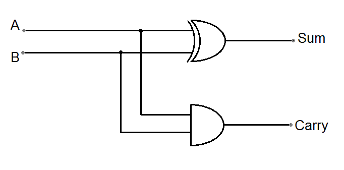
This is a combinational circuit that is designed to add 2 bits and give the sum and the carry bit. So there is 2 inputs and 2 outputs
We can take the summing and the carrying section separately and construct it using basic logic gates.
The Carry bit can be represented using a simple AND gate as both inputs must be 1 to make it 1
The Sum bit can be represented using an XOR gate. It easy to draw a xor gate, but questions may construct the XOR gate using other gates.
Full Adders
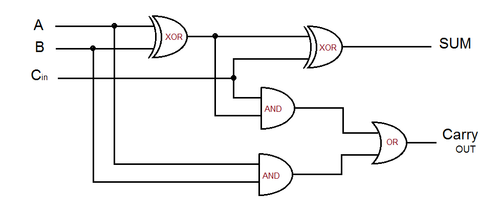
They are used to add a series of bits together. For example, 2 binary numbers that have more than 1 bit each.
So it is two half adders combined to make a full adder. The full adder takes 3 inputs, the two input bits and a carry input bit from the previous carry output bit. This will output the new carry out bit and sum bit
Note that you can get the impression that full adders are part of sequential circuits but they are not. There are no explicit links between the input and output points
The Output is directly dependant on the input and the previous output bit
So there is a direct link between the input and output side. We will learn now 2 main types of sequential circuits:
You can use either a NOR or NAND gate for this but the most common is the NOR Gate
First note down these rules:
NOR GATE:
When one of the input bits is 1 then Output is always 0
When both are 0 then Output is always 1
Please look at the logic gate below
| A | B | Output |
|---|---|---|
| 0 | 0 | 1 |
| 0 | 1 | 0 |
| 1 | 0 | 0 |
| 1 | 1 | 0 |
Here is a common diagram of a SR flip flop
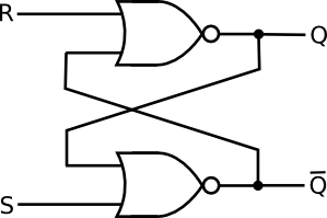
We will ASSUME that initially the output bit Q is 1 and Output bit for Q is 0
Remember that we always need the previous values Q and Q to continue the tracing or truth table for the system. Below is the truth table
| R | S | Q | Q |
|---|---|---|---|
| 0 | 0 | 1 | 0 |
| 0 | 1 | 1 | 0 |
| 1 | 0 | 0 | 1 |
| 1 | 1 | 0 | 0 |
It's always better to have an order or fixed flow of data. Start from the top R which gives Q and then it goes down and compares with S to give Q. Better to remember it like this!
Also Note that the Q and the Q is used in the next cycle for the new sets of R and S. Remember that R is compared with Q and S with Q. This may change depending on different diagrams
The flow is a ZIG ZAG movement from previous Q to next Q
There is a rule you need to remember and that is that Q and Q must be inverted so both can not be the same. Then why is the last condition both 0. This is in fact an errornous state where the bits are invalid. There are measures taken to prevent both S and R being 1 or else this is an error
More advanced version of the SR flip flops and this has 3 inputs as it has an additional input called clock or pulse
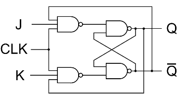
We usually use NAND gates for JK flip flops. So let us see the truth table of a NAND gate
| A | B | Output |
|---|---|---|
| 0 | 0 | 1 |
| 0 | 1 | 1 |
| 1 | 0 | 1 |
| 1 | 1 | 0 |
Only when both inputs are 1 the output is always 0
So if one of the inputs are 0 then the input is always 1
Let us now see the truth table for JK flip flops
It is not required to have 8 columns as we will only see the outcomes when the clock is 1, If it isn't 1, the JK flip flop is inactive or not started
| Clock | J | K | Q | Q |
|---|---|---|---|---|
| 1 | 0 | 0 | 0 | 1 |
| 1 | 0 | 1 | 0 | 1 |
| 1 | 1 | 0 | 1 | 0 |
| 1 | 1 | 1 | Toggles | Toggles |
You can't trace the first set of Q and Q as they are given
The meaning of toggle is somewhat confusing, it means the value of Q and Q is switched from the previous Q and Q states. This means if the before state is 0 for Q and 1 for Q then the value for Q is now 0 and Q is 1
Uses of Flip Flops
Used in memory to store the previous bit
Advantages of JK flip flops over SR flip flops
1. JK flip flops can be synchronised and started when both J and K input bits arrive by setting the clock to 0 while inactive
2. JK flip flops do not have error states instead it has a toggle state
Boolean Algebra Laws
Logic Circuits can be simplified to simpler circuits so you can use less gates and circuits. Using Boolean Algebra we can simplify large boolean expressions to simpler expressions for example:
A AND ( A AND B )
Can be simplified to:
A AND B
#So this uses less gates
Booloean algebra is written using special notations such as . for AND and + for OR and Overline for Complements or NOT
It is required that you memorise this table
| Name of Law | AND Form | OR Form |
|---|---|---|
| Identity | 1.A=A | 0+A |
| Null | 0.A=0 | 1+A=1 |
| imdemponent | A.A=A | A+A=A |
| Inverse | A.A=0 | A+A=1 |
| Distributive | A+B.C=(A+B)(A+C) | A(B+C)= A.B+A.C |
| Absorption | A(A+B)=A | A+A.B = A |
| De Morgan's | A.B=A+B | A+B=A.B |
Some laws are hard to predict such as the distributive law, we will prove it!
(A+B)(A+C)
A.A + A.B + A.C  + B.C
 A   + A.B + A.C + B.C
 //USE ABSORPTON LAW NOW
 AS A(1+B)=A
      A  +    A.C + B.C
               A +  B.C
Solving and simplify boolean algebra are like normal algebra, you do not have to put A.B but can write it as AB. All the complex laws are derived from the top laws, so please remember the basics
K-MAPS
Is the Graphical method for simplifying boolean algebra or logic circuits
Most of the time, they will give a truth table and tell us to draw the K-Map table. To do this we need to understand the sum of products
You know that the truth table considers all the outcomes of a logic gate. Likewise the sum of product is the sum of all possibilities in a written form. For example, look at the AND GATE truth table
| A | B | Output |
|---|---|---|
| 0 | 0 | 1 |
| 0 | 1 | 1 |
| 1 | 0 | 1 |
| 1 | 1 | 0 |
I will not show the diagram of this truth table and we will use Boolean Algebra to simplify this
Forming the Sum of products
             We need to convert the above to the sum of product form
             We only consider the ones that give the outcome one. If the input value is 0 then we need to put a dash on top as it is complement or NOT

              A.B+A.B + A.B+A.B
Simplifying using Boolean Algebra
            A.B+A.B + A.B
            A(B+B) + AB
            A + AB
			This is called reversing the absorption law
			A + AB+ AB
			A + B(A + A)
			A + B
			Use De Morgan's Law
			A.B
			So this is the NAND GATE
Let us see another example where we can use K-maps
ABC + ABC +ABC +ABC
The place where is it NOT then we consider it as 0
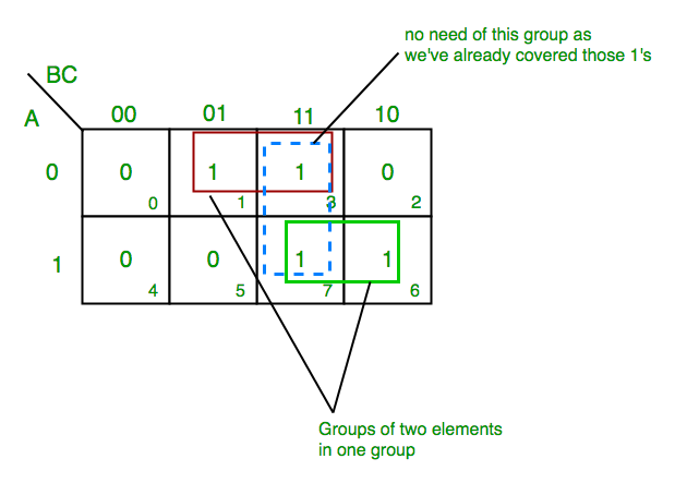
The format is very important for the K-MAP table as the order on how you arrange matters. So remember it is 00 01 11 10 for two input on one side
Also you only can circle pair or 1's that are in groups of 2, 4 or 8 or 16 and that's all. In the above example, there are 3 groups of 2's.
You always take the highest group number rather than splitting them
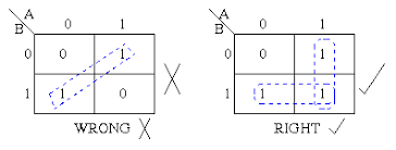
In some scene, we can circle from one side and continue on the other side as it acts like a cyclic shift like this
Also you can't circle diagonally like this
So back to the example again:
So now so for each group we need to do it like this
			ABC + ABC + ABC
			001     011      111
			011     111      110
			Now for each Column we need to see what is same

			AC +BC + AB
			01    11     11
			01    1 1    11
			If the row is 0 we put a dash over it
			AC +BC + AB
			This the simplified expression
They can ask you for 4 inputs, then it is 4 by 4 which has 16 slots!
Recommended
These are things you might like. Clicking these ads can help us improve our free services in the future...