Physics AS
Introduction Physical Quantities & Base units Vectors & Scalars Kinematics Pressure & Density Dynamics Momentum Energy, power & efficiency Deformation of solids Waves Superposition Stationary waves Electric fields Electricity Circuits & Kirchoff's laws Radioactive Physics AS PracticalPaper 5More
Reference Pastpaper Questions
DC Circuits & Kirchoff's Laws
Kirchoff's 1st Law
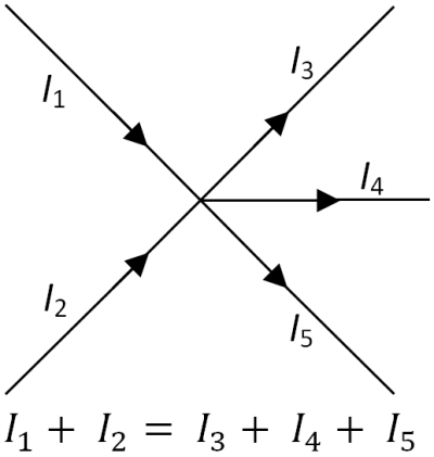
The total current entering a point must be equal to the total current leaving at the same point
This Law uses the law of conservation of charge
So actually current splits when it passes through a junction. The less resistance path way has the greatest current
Kirchoff's 2nd Law
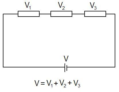
The Sum of the EMF in a loop must be equal to the Sum of potential differences across the same loop.
So this follows the law of conservation of energy as the energy gained must be equal to the energy lost
The direction of the Emf of the battery does matter.
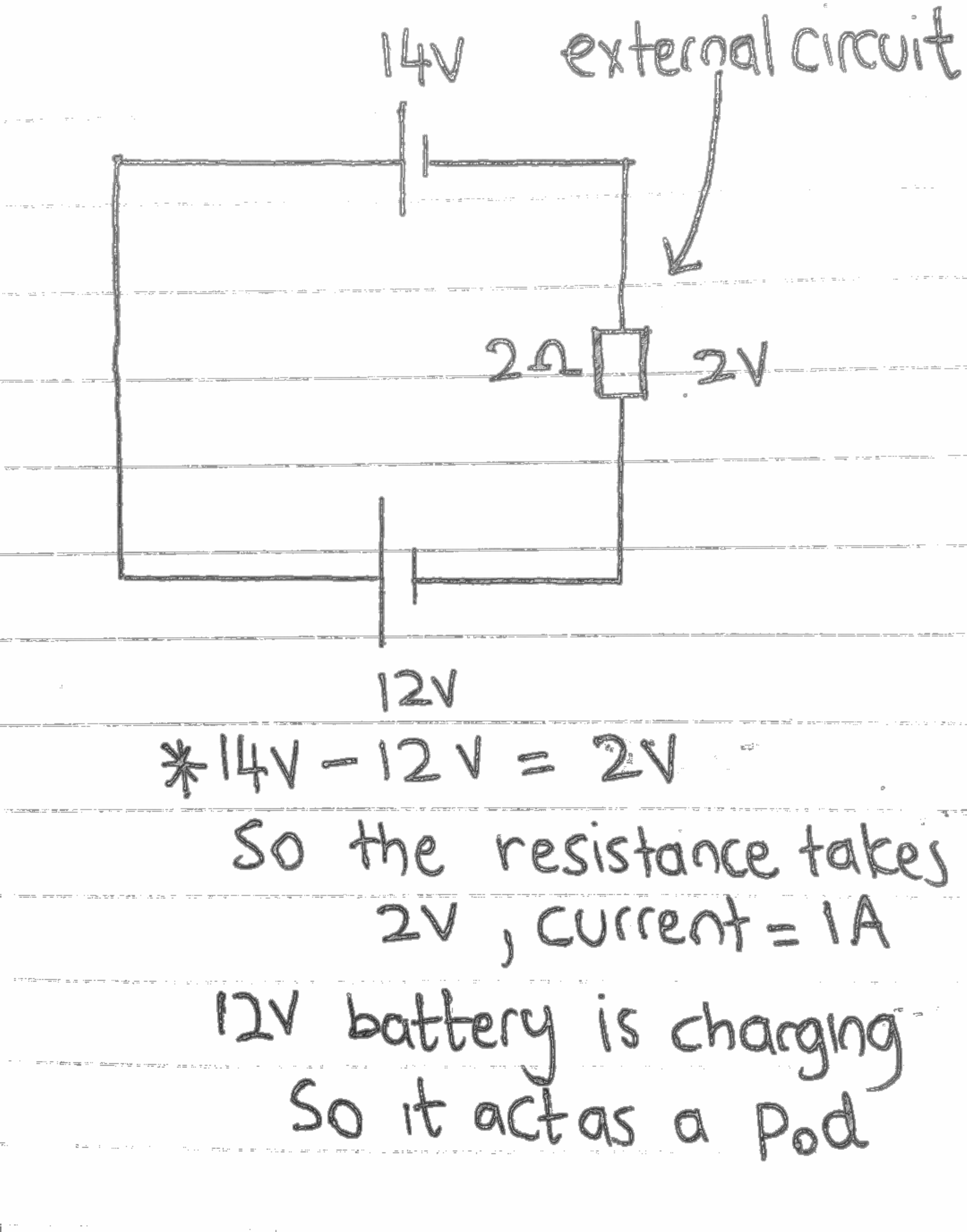
If 2 or more batteries are in a loop, we need to find the sum of the Emfs (taking the sign into account)
Actually that missing P.d is occupied by the lower Emf battery and it charges the lower Emf battery. So the resultant Emf is the Emf to be occupied by the external circuits
Now by applying the 2nd law we know that the P.d sum must equal to the Sum of the emfs
V = IR
We need to find the current which passes through a particular resistance. This is done by using Kirchoff's first law.
After finding the P.D occupied by the total resistance across a single loop, this must equal to the sum of emfs
For a simple circuit which is in series, we know that current remains constant!
EMF = IR1 + IR2
However, when there are many loops we get different currents
How to find power
Power is always calculated the same way. If we need to find the power released by the circuit, we use I2R
If we want to calculate the power of the battery, we use the EMF of that particular battery * the current it passes through
Power = VI
Why don't we use the net Emf? This is because, we find this net Emf to find the Emf across the external circuit only, Not including the batteries.
Actually the larger battery supplies it full power. However, the Emf of the second battery, which is lower than the 1st becomes a potential difference as part of the bigger Emf. In other words, the larger Emf is used to charge the smaller battery!
If both Batteries are in the same direction they provide a greater Emf and there is no charging happening
Resistance Derivation
RTotal = R1 + R2
This derivation uses Kirchoff's 2nd law as the voltage is divided in a series circuit
IRTotal = IR1 + IR2
As current is constant, we can cancel it
RTotal = R1 + R2
1/RTotal = 1/R1 + 1/R2
This uses the Kirchoff's first law
So in this, current splits in parallel but, voltage is constant
ITotal = I1 + I2
V/RTotal = V/R1 + V/R2
So we cancel out the voltage
1/RTotal = 1/R1 + 1/R2
Both derivation uses the conservation of charge
This is because, in the first derivation, current remains constant and in the second derivation, current splits but the total remains constant
Internal Resistance
Usually a cell has its own resistance and thus occupies some of the EMF provided by the cell
EMF = Lost Voltage + Terminal Voltage
The Terminal Voltage is the voltage in the external circuit. So when the internal resistance is greater. The greater the Lost Volts or Voltage occupied by the internal resistance.
If we want to reduce the lost volts and increase the voltage supplied to the external resistance. The battery must contain a lower internal resistance or the current in the circuit must decrease. This is done by increasing the resistance of the external circuit
IRTotal = IRInternal resistance + IRExternal resistance
Current remains constant in a series circuit
We just assume that the internal resistance acts as a normal fixed resistance
Potential divider
So as we discussed:
V ∝ R
Greater the resistance, greater the potential difference it occupies.
And we also discussed how to find the Voltage occupied by the resistance compared to the total resistance in a circuit.
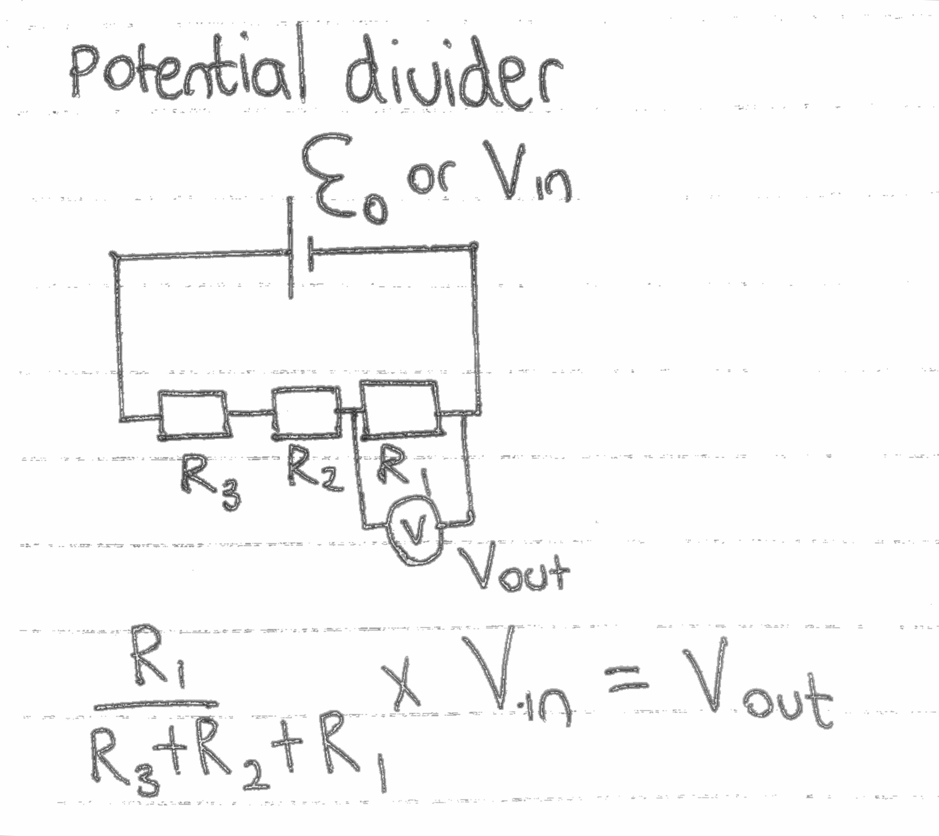
VOut = VIn * R1/R1+R2
So we find the ratio of the particular resistance compared to the whole resistance of the circuit.
This could be applied for internal resistance to find lost volts
Potentiometer
In this, we need to know some new terms:
- Driver cell
- Unknown cell
This is known as the main cell in the circuit
This is the cell which the emf is to be found or compared
This is an example of a potentiometer circuit
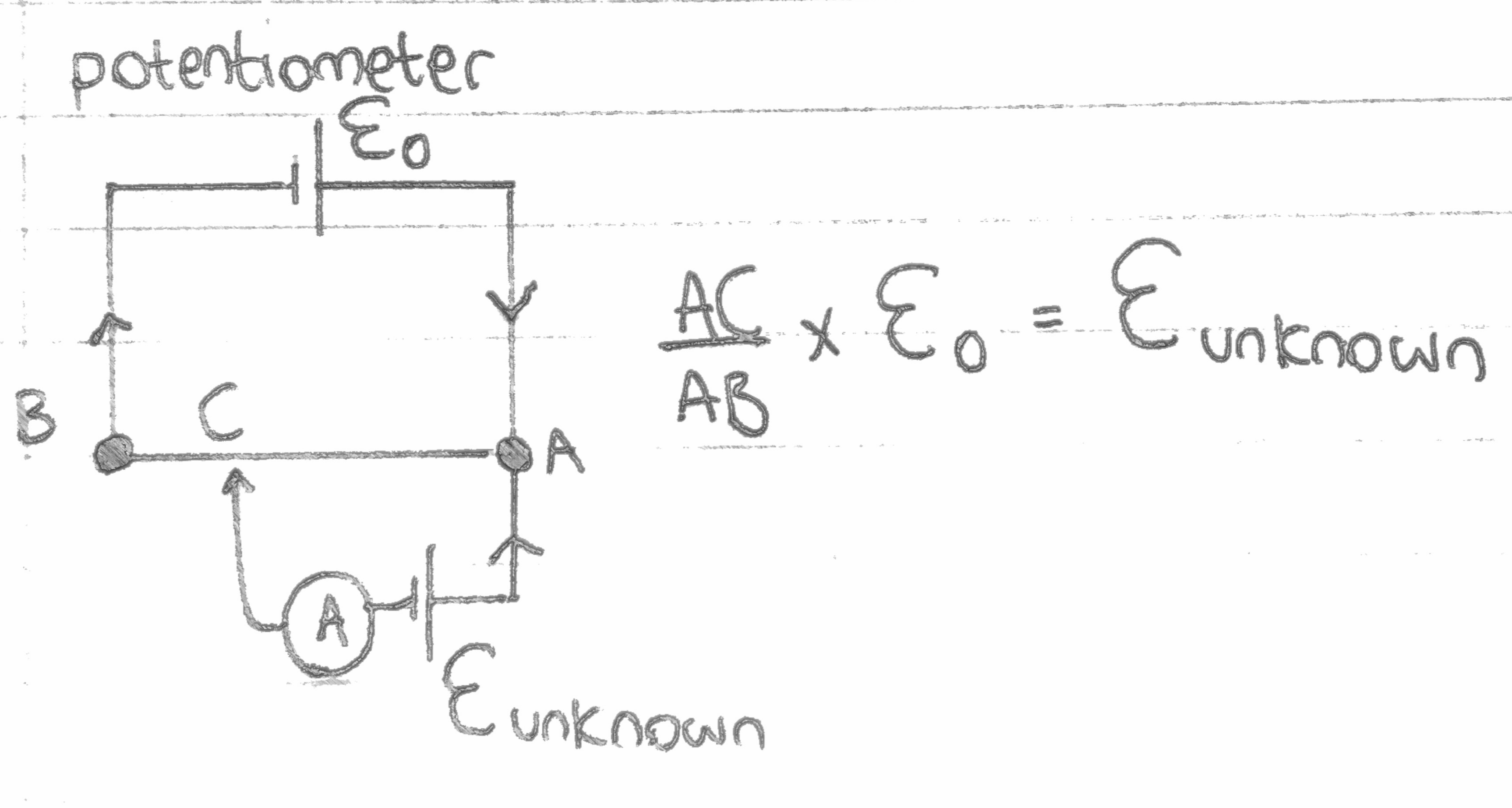
Notice how the unknown cell is in the opposite direction of the driver cell.
You will need to know this! Usually wires are assumed to have 0 resistance. However, Wire AB contains a significant amount of resistance.
Also the Resistance of the wire increases linearly when the Length of AC increases.
So we know that when the resistance increases the Voltage occupied from the driver cell increases and so for a certain length of AC, the Voltage occupied from the driver cell is equal to the unknown cell EMF
Because the batteries are in the opposite direction and the Voltage occupied from the driver cell is equal to the EMF of the unknown cell, they cancel out each other giving a net Emf of 0V and so the galvonometer or the ammeter will show a zero reading and there is no potential difference or current in the smaller circuit.
So For most questions. There are no other resistance or internal resistance. And Assuming all the potential difference is occupied by the Wire AB, the ratio of AC and AB will tell us how much Voltage is occupied.
EMFunknown = EMFDriver Cell * AC/AB
This only happens when the ammeter is zero
However, some question do have internal resistance and a fixed resistor. Like the one below
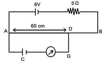
In this case, it becomes a bit complicated
The Unknown cells internal resistance can be neglected. This is because, when the current is zero in the smaller cirucit. The lost volts is Zero
Due to this internal resistance in the driver cell, we place a voltmeter Across the Wire AB (The full Wire). So then we can apply this equation again. However, keep in mind that when the Contacts is moved from A to B, The voltmeter reading changes
EMFunknown = Voltagevoltmeter * AD/AB
This also could be used to compare two or more Unknown cells to see which one has the greater EMF
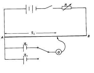
Which ever uses the greatest length of wire to make the ammeter zero has a higher EMF. This is because, more Voltage must be occupied in order to cancel the unknown cell EMF
DC Circuits
You will need to know some of the components in common circuits and their properties
LDR
This is known as the light dependant resistor
The resistance of the component decreases when the light intensity increases and so the current flow of the circuit increases and also the voltage occupied by the component decreases
This is used in potential dividers
Thermistor
We usually talk about the negative Thermistor cofficient(NTC)
The resistance of the component decreases when the temperature increases and so the current flow increases and the voltage occupied decreases
Ohmic Device
An Ohmic device is a device which follows Ohm's law and we need to know the graph
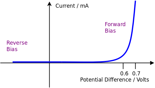
Diode
A diode is a component which only allows current pass in one direction. It has a low resistance when the current flows in forward-bias.
When the current is reversed this is known as the reverse bias and the resistance is almost infinity
When the current flows in forward bias and reaches a certain voltage known as the key value (0.6v) the resistance decreases exponentially
Filament Bulb
When the current flow increases, the temperature increases and so the resistance increases and causes the graph to curve
This graph is current against voltage so the gradient is 1/r
So when the gradient decreases, it means the resistance is increasing
Easy way to remember is that this is like a S curve graph
Recommended
These are things you might like. Clicking these ads can help us improve our free services in the future...
End of Chapter Videos
Collection of Videos to Support Your Understanding.
Remember these videos are handpicked by me and I feel these are the best ones out there. But I constantly update this list for each chapter. The Youtubers are more than welcome to contact me.
Also, don't forget to Subscribe to our Youtube channel - MrWik
Watch